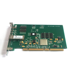
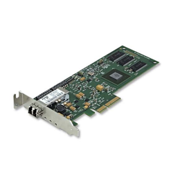
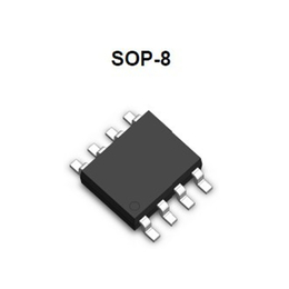
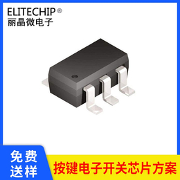
STM8S003F3P6 STM32F103C8T6
¥3.6元/件
中国 广东 深圳
来电请说明在第一枪看到,谢谢!
LCD parallel interface
The FSMC can be configured to interface seamlessly with most graphic LCD co*ollers. It
supports the Intel 8080 and Motorola 6800 modes, and is flexible enough to adapt to
specific LCD interfaces. This LCD parallel interface capability makes it easy to build cost-
effective graphic applicati* using LCD modules with embedded co*ollers or high-
performance soluti* using external co*ollers with dedicated acceleration.
2.3.7
Nested vectored interrupt co*oller (NVIC)
The STM32F103xC, STM32F103xD and STM32F103xE performance line embeds a nested
vectored interrupt co*oller able to handle up to 60 maskable interrupt channels (not
including the 16 interrupt lines of Cortex™-M3) and 16 priority levels.
●
Closely coupled NVIC gives low latency interrupt processing
●
Interrupt e*y vector table addres*ssed directly to the core
●
Closely coupled NVIC core interface
●
Allows early processing of interrupts
●
Processing of late arriving higher priority interrupts
●
Support for tail-chaining
●
Processor state automatically s*ed
●
Interrupt e*y restored on interrupt exit with no instruction overhead
This ha*are block provides flexible interrupt management features with minimal interrupt
latency.
2.3.8
External interrupt/event co*oller (EXTI)
The external interrupt/event co*oller c*ists of 19 edge detector lines used to generate
interrupt/eve*equests. Each line can be independently configured to select the tri*er
eve*ising edge, falling edge, both) and can be masked independently. A pending register
maintains the status of the interrupt requests. The EXTI can detect an external line with a
pulse width shorter than the Internal APB2 clock period. Up to 112 GPIOs can be connected
to the 16 external interrupt lines.
2.3.9
Clocks and startup
System clock selection is performed*tartup, however the internal RC 8 MHz oscillator is
selected as default CPU clock on reset. An external 4-16 MHz clock can be selected, in
which case it i*onitored for failure. If failure is detected, the system automatically switches
back to the internal RC oscillator. A software interrupt is generated if enabled. Similarly, full
interrupt manageme*f the PLL clock e*y is *ailable when necessary (for example with
failure of an indirectly used external oscillator).
Several prescalers allow the configuration of the AHB frequency, the high speed APB
(APB2) and the low speed APB (APB1) domains. The maximum frequency of the AHB and
the high speed APB domains is 72 MHz. The maximum allowed frequency of the low speed
APB domain is 36 MHz. See Figure 2 for details on the clock tree
以上内容为STM8S003F3P6 STM32F103C8T6,本产品由深圳市斯瑞特科技有限公司直销供应。
声明:第一枪平台为第三方互联网信息服务提供者,第一枪(含网站、小程序等)所展示的产品/服务的标题、价格、详情等信息内容系由会员企业发布,其真实性、准确性和合法性均由会员企业负责,第一枪概不负责,亦不负任何法律责任。第一枪提醒您选择产品/服务前注意谨慎核实,如您对产品/服务的标题、价格、详情等任何信息有任何疑问的,请与该企业沟通确认;如您发现有任何违法/侵权信息,请立即向第一枪举报并提供有效线索。我要举报


