
成都北亿纤通科技有限公司
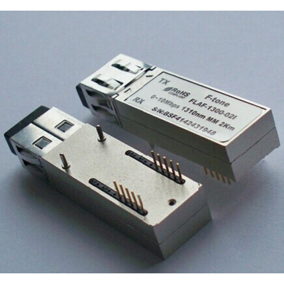


飞通PT7323-32-1光模块
产品属性
- 兼容品牌:
- 飞通NeoPhotonics
- 封装类型:
- SFF
- 传输速率:
- 155Mb/s Single Mode
- 品牌:
- 其他
- 型号:
- PT7323-32-1
- 类型:
- 行业标准
- 电压:
- 3v
- 功率:
- 30km with 9/125µm single mode fiber
Specificati*
- 产品型号: PT7323-32-1
- 兼容品牌: 飞通NeoPhotonics
- 封装类型: SFF
- 传输速率: 155Mb/s Single Mode
- 传输距离: 30km with 9/125µm single mode fiber
- 发射波长: 1310nm
- 接收波长: 1310nm
- 工作温度: 商业级0℃~+70℃/工业级-40℃~+85℃ 可选
- 数字诊断: 带DDM/不带DDM 可选
- 发射光功率: 30km with 9/125µm single mode fiber
- 接收灵敏度: 30km with 9/125µm single mode fiber
Description
PT7323-31-1
Small Form Factor 155Mb/s Single Mode 2×5 Transceiver
1 Features
1.1 Transceiver unit with independent
1310nm MQW FP Laser diode tran*itter
InGaAs PIN photodiode receiver
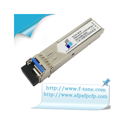
1.2 Meet SFF MSA with duplex LC recept*e
1.3 Metal enclosure for lower EMI
1.4 +3.3V Single power supply
1.5 Qualified to meet the inte*f Bellcore reliability practices
1.6 LVPECL logic interface simplifies interface to external circuitry
1.7 Links of 30km with 9/125µm single mode fiber (SMF)
2 Applicati*
2.1 SONET OC-3 IR-1 / SDH STM S-1.1
2.2 Fast Ethernet
3 General
PT7323 transceiver is a high performance, cost effective module for serial optical data communication
application.
3.1 Tran*itter Section
Tran*itter is designed for single mode fiber and operates at a nominal w*elength of 1310nm. The
tran*itter module uses a MQW FP laser diode and full IEC825 and CDRH class 1 eye safety. The
output optical power can be disabled via the single TxDis pin. Logic LVTTL HIGH level disables the
tran*itter. It contains APC function, temperature compensation circuit, PECL data inputs, LVTTL TxDis
input interface.
3.2 Receiver Section
The receiver section uses a hermetic packaged PINTIA (InGaAs PIN and trans-impendence amplifier)
and a limiting amplifier. Which transforms input optical power to optical current through PIN PD. And the
optical current is transformed to voltage signal bytrans-impendence amplifier. Differential DATA and
/DATA LVPECL data signal that is open emitter output is produced by limiting amplifier and voltage
signal that is through limiting amplifier and filter. The receiver signal detect monitors input optical signal.
When the optical power is not enough to support module operating normally, SD pin will beat LVPECL
logic level 0 and signal detect appears. The PINTIA is ac coupled to limiting amplifier through a low pass
filter. The LPF are enough to pass the signal from 5Mb/s to 200Mb/s without significan*stortion or
performance penalty.
3.3 Power Supply Filtering and Ground Planes
It is important to exercise care in circuit board layout to achieve optimum performance from these
transceivers. It is further recommended that a continuous ground plane be provided in the circuit board
directly under the transceiver to provide a low inductance ground for signal return current.
3.4 Electromagnetic Interference (EMI)
One of a circuit board designer’s foremost concerns is the co*ol of electromagnetic equipment.
Success in co*ollin*enerated Electromagnetic Interference (EMI) enables the designer to pass a
governmental agency’s EMI regulatory standard and more importantly, it reduces the *sibility of
interference to nei****oring equipment. PT7323 provides excellent EMI performance. PHOTON LC
transceiver use forward and backwa*hields, which obturates the interstice of LC module effectually,
and improves EMI performance.
3.5 Application Note
There are a few fundamental guidelines to follow when designing the PT7323 circuit interface. On the
board, every data connecti*hould be an impedance match. The data inputs and outputs lines should
be treaded as 50ohm microstrip line, and vias should be *oided. The matching resistor should be
placed at the end of each matched line. The PT7323 is high frequency, hi****andwidth circuits. To
ensure stability, use good high frequency layout techniques, filter voltage circuit, and keep ground
connecti* short.
4 Performance Specificati*
Cauti*tresses in excess of the absolute maximum ratings can cause catastrophic damage to the
device, all parameters h*ing values within the recommended operating conditi*.封装类型